Barry Bogs

Union Pacific  FEF-3

in  1/22.5  Scale
Barry Bogs Union Pacific FEF-3 in 1/22.5 Scale |
|
|
|
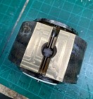
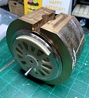
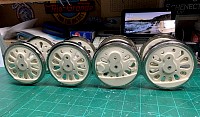
The Drivers -
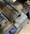
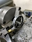
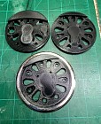
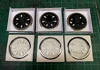
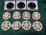
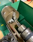
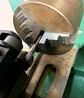
July 10th, 2022 Drivers are the key to an project that the BLW shops want to build. No drivers or wheels, no project, period... Thank goodness for the kind folks at K and D Casting and machine works . I was able to use the large lathe in his shop to turn the tires for the FEF3 project. In face, a total of 16 tires were made during that session, 8 of which are for future projects. With the tires made from steel tube, each had to be cut off the pipe, as the first picture shows. Once the ring was chucked into the lathe, then the manual machining took place. This takes many hours of lathe time and lots to clean up after all the metal comes off. A groove on the inside of the tire is the last thing to be cut. This grove locks the wheel to the tire, once the wheel is cast. The tires are then sent out to a plating company here in the Houston area to be nickle plated. The wheels were designed in Solid Works 3D design software by the boys in the Cumberland Model Engineering shop. There is a lot of info on the drivers available that aided the CME guys to create the three different drivers. Since the CME folks are in TN, I needed the driver prints from someone who is local. The boys at Buckley's 3D Printing shop stepped up to the plate, and had the drivers printed in no time at all. I added the tires to the black prints and made the molds of each. Once the molds were made, the tires were placed in the mold and two part urethane was poured into it. All eight drivers are shown next to the masters in the final picture. From here, the axle and crank pin holes will need to be drilled in the castings. The problem now, is that the BLW shop does not have a large enough lathe to tun the drivers, so finding one locally is the next issue. The next step, the axles and quartering the driver wheel sets. The boys in the machine shop were able to find a friend of BLW down the street from the shop that had a lathe large enough to be able to center drill the drivers for the axles. Of course the in house lathe was large enough to make the axles as you can see below. With the gears on the first and fourth axles, I directed the boys to drag out the quartering jig and start assembling the wheel sets. With the removable crank pins installed in the jig, the boys pressed one end of the axle into the first driver, and then placed the second driver on the other side of the jig. The second driver was then pressed onto the other end of the axle. The crank pins were pulled out and the driver set was pulled out the slot in the quartering jig. The boys assembled the other driver sets after that. The jig is the correct width so that when the drivers are pressed on, they are in gauge and no other adjustments are needed. The boys in the machine shop will make the crank pins for the drivers next, with the shop lathe, out of 3/16" brass rod. These will be drilled for the crank pin screws to hold the rods on with and knurled on the other end to hold in the driver. Fun times in the BLW shop! I just love it when a plan comes together and building choo choo's is one of the best plans in my book! Well, there you have it. Full speed ahead here. - Barry |
 |
 |
 |
 |
 |
 |
 |
 |
 |
 |
|
|
switch to the progress photos in this series |
|
|
|
to the FEF-3 Project page | the C&W Home Page |
|